AODEQI · BUYING & APPLICATION GUIDES
Rotary Axis for Laser Marking: Cylindrical Parts Marking Guide
Choose a rotary axis for rings, tubes and cylindrical parts. Check holding, controller compatibility, focus, artwork and complete-cycle acceptance.
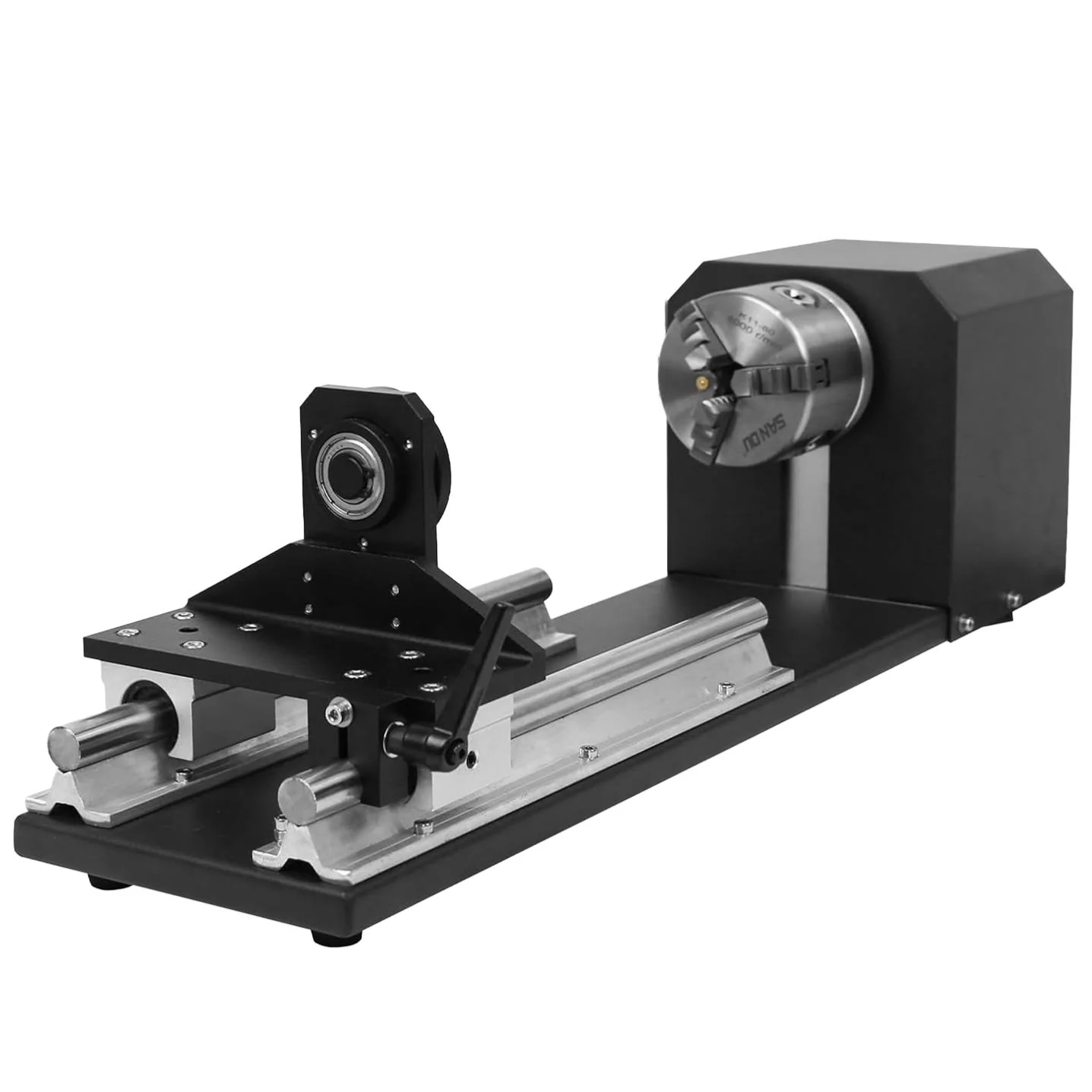
A rotary axis can help a laser marking system identify rings, tubes, cylindrical tools and other curved parts. However, an accessory that physically rotates a component is not automatically compatible with every controller or application. The correct choice depends on part geometry, mass, access, required artwork and the way rotation is coordinated with the marking process. This guide explains the questions a buyer should resolve before ordering a rotary accessory and the checks needed to turn a successful demonstration into a reproducible production arrangement.
Decide whether rotation is actually necessary
Identify geometry and access
A small identifier on an accessible portion of a large-radius surface may be evaluated without continuous rotation. A wraparound design, an inner-ring inscription or information distributed around a cylinder can require a different arrangement. Describe the actual marked area rather than only the overall part shape. The supplier needs to know whether the task involves one short line, a broad logo, several indexed positions or a continuous pattern. Ask for an assessment of focus, geometric distortion and access before assuming that a rotary axis is either essential or sufficient.
Describe the component and holding requirements
Confirm fixture and controller compatibility
Provide the part's minimum and maximum diameter, length, mass, wall thickness and surface finish. Include drawings or photos showing the available clamping surfaces and any area that must not be marked or damaged. A chuck-based fixture and a roller arrangement interact differently with delicate, irregular or low-friction pieces. Long or unbalanced parts may need support beyond the rotary unit itself. Ask the supplier to confirm the allowable load and the proposed holding method for your actual component, rather than relying on the appearance of an accessory in a catalog photograph.
Confirm controller and software compatibility
The accessory's motor, drive, connections, positioning behavior and software support must match the marking system. Identify the controller and software used on the machine being quoted or retrofitted. Confirm whether the task requires indexed marking, synchronized rotational marking or another supported operating method. Do not describe an accessory as universally compatible because its connector resembles an existing socket. Ask what setup information, calibration procedure and training are supplied and whether the proposed configuration has been demonstrated with the same controller and intended marking sequence.
Plan artwork around the developed surface
When a design extends around a cylinder, its flat artwork must be related to the actual developed surface. The relevant diameter and artwork dimensions need to be entered according to the selected software's procedure. An incorrect value can distort characters or create a mismatch where the pattern joins. Tapered, stepped or irregular surfaces require additional assessment; a simple cylindrical setup may not be adequate. Supply the real artwork and define whether a join, gap or repeated segment is acceptable. Verify the result on a representative part rather than approving only an on-screen preview.
Check focus and physical access
The laser still needs suitable access to the surface being marked. Confirm the working distance, height adjustment, available clearance and the relationship between the rotary axis and marking head. Inner-ring work can create different access constraints from external tube identification. A large part may interfere with the machine structure or enclosure even when it fits the accessory's nominal diameter range. Include the proposed fixture and supporting hardware in the demonstration. The complete arrangement should provide a reproducible way to establish position and focus without relying on an operator's visual estimate.
Evaluate the complete cycle and code result
Record loading, clamping, locating, any rotational positioning, data transfer, marking, checking and unloading. If multiple positions are marked, confirm the indexing sequence and its relationship to the part record. For a machine-readable identifier, evaluate the code in the orientation, curvature and reading conditions expected in use. A flat sample can remain useful for initial process development, but it cannot establish that a wrapped or indexed result is readable on the actual component. Agree how a slipped part, incomplete sequence or failed reading is detected and handled.
Match the source to the material separately
A rotary axis changes handling; it does not change which material interaction a source can achieve. A metal ring may lead to fiber or MOPA testing, while another material may require a different technology. Specify the alloy, coating and desired surface effect along with the geometry. If the part is valuable or delicate, agree the sample and acceptance procedure before testing. Required depth, contrast, surface condition and any subsequent polishing or finishing should all be part of the evaluation, not left until the accessory has already been purchased.
Include the complete installation in the quotation
The quoted scope should identify the accessory, controller compatibility, required support fixtures, focus arrangement and operating instructions. Confirm the suitability of the enclosure, guarding, interlocks and extraction for the combined setup. Ask which assembly and calibration tasks belong to the supplier and which must be completed on site. If the accessory is added to an existing machine, provide the machine identification and configuration details before ordering. A separate accessory purchase is most useful when its integration and acceptance responsibilities are as clearly defined as its mechanical dimensions.
Prepare an acceptance sample and setup record
Use the intended part and real artwork to approve orientation, position, character shape, join quality, surface condition and full cycle. Record the fixture, diameter entry, source settings, focus method and relevant software configuration. Keep the approved sample and setup instructions together. Review whether different product sizes require separate settings or fixtures and identify the limits of the approved range. This helps operators repeat the process and makes it easier to distinguish an artwork issue, a slipping part and an incorrect configuration when troubleshooting a later variation.
Request an accessory matched to the job
Send AODEQI the dimensions, mass, material, photos, marking file and machine-controller details. Explain whether you need inner engraving, an external identifier, indexed locations or wraparound artwork. Review the laser marking accessories page and arrange a sample evaluation where the result is uncertain. The right rotary arrangement is the one demonstrated on your component and supplied with a clear setup and acceptance procedure, not simply the accessory with the widest advertised diameter range or the lowest standalone price.