AODEQI · BUYING & APPLICATION GUIDES
How to Mark Stainless Steel: Best Laser Settings & Tips
Develop stainless steel laser marking settings through controlled tests of material, focus, pulse parameters, contrast and finished-part requirements.
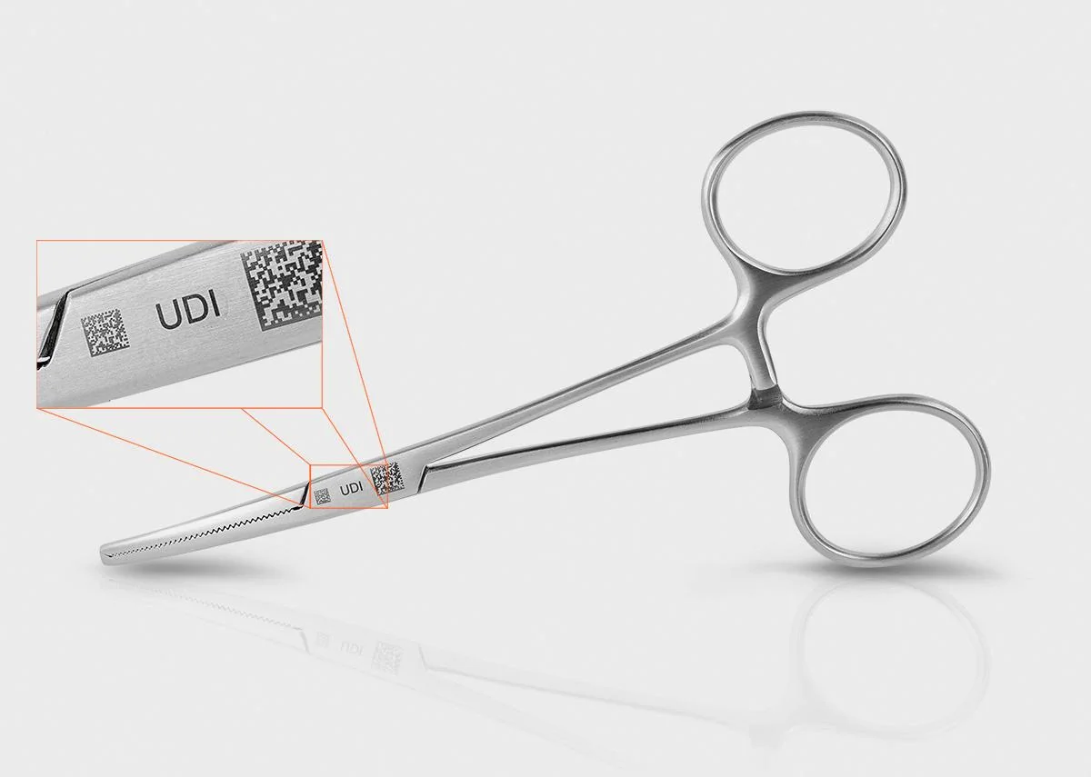
The best laser settings for stainless steel depend on the actual grade, finish, mark geometry and required surface condition. A polished instrument, brushed nameplate and machined housing can behave differently even when all are described as stainless steel. Copying an online power-and-speed recipe can therefore create an attractive but unsuitable result. This guide explains a practical development method for a qualified operator: define the result, select an appropriate source, vary settings in a controlled way and validate the finished part before releasing a production recipe.
Separate identification from deep engraving
Material identification and finish
Start by deciding whether the objective is a dark contrast mark, a light surface effect, a recessed identifier or decorative color. Each changes how the process should be developed. A production drawing may prohibit material removal on a functional surface, while another application may require physical depth. Specify the permitted marking location and any restrictions on roughness or dimensions. For medical and corrosion-sensitive components, the final validation must also address the material's intended use; a visually dark mark is not by itself evidence of acceptable surface performance.
Confirm the machine and material combination
Define a useful test reference
Record the stainless grade, surface finish, cleaning condition and any prior treatment. Record the source model, power class, scanner, lens, marking field and focus arrangement. Fiber marking machines are a common starting point for stainless identification and engraving. MOPA fiber configurations offer additional pulse control for selected contrast or color requirements. The available settings are source dependent. A parameter file made for one pulse architecture, lens or software interpretation may not transfer directly to another machine, even if both carry the same nominal wattage.
Understand the settings that work together
Average power, travel speed, pulse repetition, available pulse duration, hatch spacing and pass count interact. Changing frequency can alter the energy delivered in each pulse within the limits of a particular source. Hatch spacing changes how adjacent scan lines cover an area. Multiple passes can increase processing time and cumulative surface exposure. Focus position and the selected lens affect the working spot. Treat these as a coordinated process rather than independent sliders. Ask the supplier to explain the usable operating range of the exact source instead of assuming all displayed settings are equivalent.
Establish a repeatable starting condition
Use clean representative test pieces, an approved fixture and the focus method supplied for the machine. Confirm that the extraction and complete workstation are operating as intended. Use the actual font, line thickness, code dimensions and fill pattern where possible; a large test square may not predict the quality of tiny characters. Identify each sample before testing so the result remains connected to its settings. Qualified personnel should follow the machine's operating and safety instructions throughout development, including guarding and restrictions on reflective workpieces.
Build a controlled test matrix
Begin with a supplier-supported starting recipe for the intended effect. Change one factor at a time or use a planned small matrix with clearly labeled combinations. Keep the material, artwork, fixture and inspection conditions constant. Do not combine unrecorded changes to power, frequency and focus and then attempt to guess which produced the improvement. Retain unsuccessful samples as well as acceptable ones. They show where the process becomes too weak, visually inconsistent or damaging and help establish a useful working window instead of a single fragile setting.
Inspect more than the immediate appearance
Compare readability, edge quality, uniformity and the permitted surface condition. Inspect from the relevant viewing or reading angles, especially on polished material. Check whether residue or cleaning changes the appearance. Where a code is required, verify its content and assess quality with the agreed equipment. Where service conditions require it, evaluate corrosion behavior, cleaning resistance or other functional properties using a suitable documented method. These evaluations should be selected for the finished device or component, rather than copied from an unrelated demonstration.
Investigate common production differences systematically
When a previously approved recipe produces a different result, first compare the part and setup with the reference record. Check material batch, finishing, contamination, focus, fixture condition and the correct artwork revision. Inspect the working environment and accessible optics using the supplier's maintenance instructions. Avoid immediately compensating with additional power, because that can conceal a changed setup or an underlying equipment issue. Save the original approved recipe before making any adjustment, and document why a change was necessary and how the revised result was accepted.
Document a production recipe that operators can use
The release record should identify the machine configuration, material, artwork, marking location, fixture, focus method and every relevant process setting. Include the approved sample, inspection conditions and measured full cycle. Add permitted variation limits and an escalation step for rejected results. If multiple operators or shifts use the station, make the correct recipe and part identification easy to confirm. Configuration control matters particularly when similar-looking products use different alloys, coatings or code content. An uncontrolled file name is a weak substitute for a clear revision and approval process.
Request a test around your real requirement
Send AODEQI the stainless grade, finish, part dimensions, artwork and desired contrast or depth. Explain any downstream processing and the complete production quantity. Through a sample marking evaluation, the discussion can focus on a demonstrated configuration and an agreed result. Universal numeric settings would imply certainty that the available information does not support. A documented test on representative parts is more useful: it establishes the process conditions, inspection method and practical limits that your purchasing and production teams can actually rely on.